Constructing the Enginehouse
|
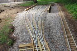
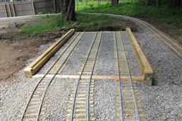
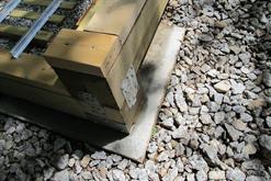
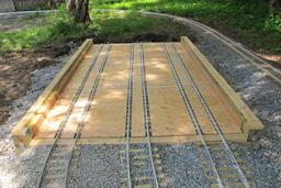
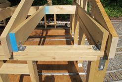
Concrete footings and pressure treated 6x6's and 3/4" stone base are all place. Track laid on the stone base. Note that the front and rear walls' 4x4 bases act as 'cross ties' and secures track to the enginehouse structure. Simpson StrongTie Connectors are used extensively in the construction.
|
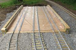
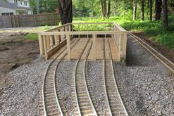
Plywood floor was installed before continuing construction. Then plastic sheeting was laid down temporarily to protect the plywood floor before the walls and roof were added.
|
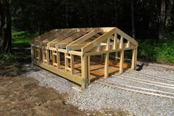
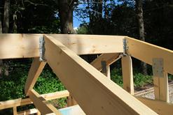
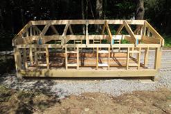
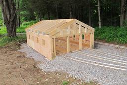
Framing underway. Note some sistered 2x4's/
|
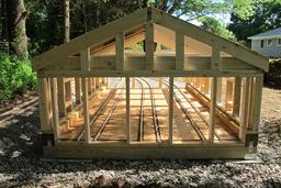
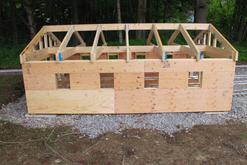
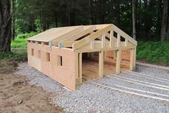
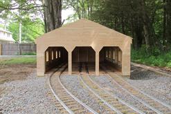
Windows are framed out and 1/2" plywood sheathing installed.
|
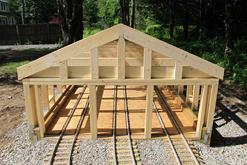
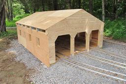
1/2" plywood installed as roof underlayment.
|
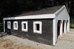
Roofing paper applied over plywood on side walls and roof. Front plywood painted. 1x6 molding pre-painted and installed under roof edge. 1x3 molding pre-painted and installed in remaining locations on the enginehouse.
|
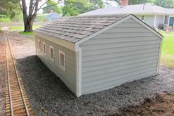
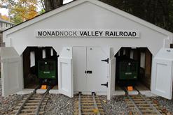
Asphalt shingles installed on roof. 4" wide siding installed on sides and rear walls. Window glass installed. 56" wide "Monadnock Valley Railroad" decal was provided by Highball Graphics and affixed to pre-painted 1x4 molding.
|
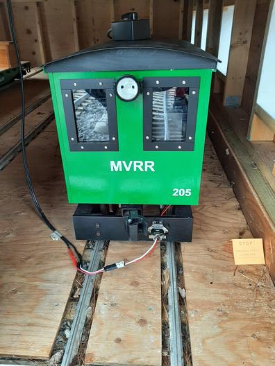
With enginehouse structure completed, cables were run from the 12 volt battery chargers in the basement of the house to inside the enginehouse and terminated with male connectors that will mate with the connectors on the front of the locomotives.
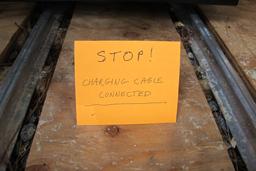
| A 'STOP!' sign is placed in from to each locomotive to remind users to turn off the chargers prior to removing the connectors in the front of the locomotive.
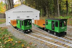
| Our two locomotives and flat cars pose in from of the completed enginehouse.
|
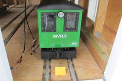
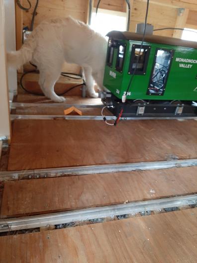
Note the charging cable connected to the front of the locomotive frame.
| Callie is confirming that all the charging cables are correct.
|
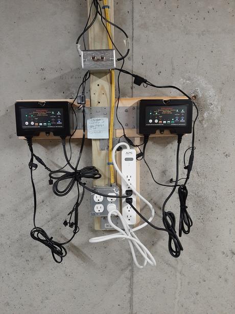
Dual 12 volt battery chargers shown mounted on basement wall for charging the locomotive batteries. These battery chargers require that the batteries be connected to the charger prior to apply power to the chargers; that's managed by the two toggle switches mounted above the chargers. The locomotives are powered by two 24 volt motors, one mounted on each axle. The MVRR uses two 12 volt deep cycle marine batteries wired in series to provide the 24 volts required by each motor. A hand-held throttle is used by the locomotive engineer to control speed and forward/reverse direction of travel.
|
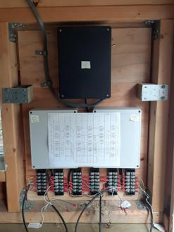
Enginehouse wiring for remote control switches
|
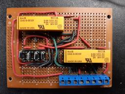
12 volt power supply and motorozed switch components ready for wiring in the enginehouse.
| Motorized switch remore control circuit ready for mounting in the enginehouse.
| Motorized switch circuits wired to track-side bush-button controls.
|
|